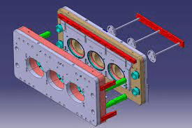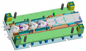
More and more companies are looking for new methods and tooling design that optimizes the manufacture of parts and products. Thanks to technology, there have been many improvements in process automation and freight transport.
Industries are producing on a large scale to meet demand and increase the customer base. However, not worrying about the quality and costs generated in manufacturing can aggressively affect the marketing of a product, right?
And how to manufacture products with agility, high quality and without additional costs? Through Design for Manufacturing (DFM), all of this is possible, with advance projections to define the layout of a product.
What is DFM? Tooling design
The Design for Manufacturing or Design for Manufacturing (DFM) is a technique focused on the parts and components. It will form a product, structuring the design and planning of the manufacturing process.
Tooling design aims to facilitate development and reduce or eliminate costs with extremely expensive, complex or unnecessary resources for production. In addition, it guarantees to improve the production of components and to compare selected materials and processes.
DFM is part of the DFMA ( Design For Manufacturing and Assembly ) methodology. Moreover, it also comes by the DFA (Assembly Design) technique. Both of which are essential for products to be designed, manufactured and marketed in a short period.
Differences between DFM and DFA
DFM and DFA are two different techniques, but they can cause confusion as they are part of the same methodology (DFMA). While DFM is focused on the analysis and selection of components, DFA evaluates the entire product, not just the parts, in order to simplify the product structure while keeping the design flexible.
Design for Assembly (DFA) also seeks the most efficient use of the functions of the components selected by the DFM process. The performance of this methodology together makes assembly less costly and more optimized.
See in the image below the main differences between these techniques:
How important is Design for Manufacturing?
The importance of DFM is to reduce manufacturing costs. About 70% of the manufacturing costs (cost of materials, processing and assembly) are determined by design, production, and process planning or machine tool selection decisions.
This technique also helps to eliminate revisions and design changes that cause delays in programming. tooling design results in less assembly time, lower costs, elimination of process waste and greater product reliability.
Check out the main benefits of Design for Manufacturing (DFM):
- Compares the use of combinations of materials and manufacturing processes selected for assembly;
- Standardizes materials, finishes and parts;
- Ergonomically shaped components;
- Delimit costs with the use of these materials and processes;
Find out what are the main internal failures that your industry may be committing.
How to run DFM in manufacturing?
Before applying DFM or tooling design, it is necessary to emphasize the need to evaluate the functions of the components well. It is always trying to reduce as much as possible the number of parts of the final product.
Reducing components in a product decreases manufacturing costs, less spending on purchases, reduces inventory, development time and improves equipment efficiency.
To do this, you can follow 3 basic questions to check the need for a particular item:
- Is relative movement necessary between the parties?
- Is there a need for material specifications for chemical / physical reasons?
In addition to this first step, there are others that are very important for you to successfully run DFM:
- Use standard parts
Standardizing parts generates fewer costs than customized items. The high availability of these components reduces delivery times and relieves pressure on production schedules.
- Multifunctional component design
Multifunctional components reduce the total number of parts in a design, improving production efficiency. An example is part acting as an electrical conductor and as a structural element. They use tooling design techniques.
3. Manufacturing design:
Choose the right combination of material and processes to lower your overall manufacturing cost. In general, final operations, such as painting and polishing, should be avoided.
The ideal design for the tooling design industry
If you want precision and quality in production, Design For Manufacturing is the right technique. With the right planning within the production line, product delivery becomes more streamlined and your industry minimizes costs.
Do not forget to form teams between tooling design and Manufacturing Engineers in the development of the manufacturing and assembly methods of the products.
What is automobile mold manufacturing and how to perform mold manufacturing?
What is automobile mold manufacturing, and how do automobile mold manufacturers carry out mold manufacturing?
Many people are now driving cars, but do you know about car mold manufacturing? If you want to think about the quality of automobiles, you must ensure the quality of automobile mold manufacturing. Then how to make automobile molds? Read the rest of the article to fix this.
First of all, let everyone know what is automobile mold manufacturing?
Generally speaking, it has to be the general term for the molds used to punch all the stamping parts on the car body. For example, the top cover flanging mold, the beam reinforcement plate pressing mold, etc.
We can call it the type of automobile mold manufacturing. There are many different classifications of automobile abrasives manufacturing, so everyone needs to choose and apply according to the actual situation. Let's get to know some common sense of classification of automobile mold manufacturing together.
How to classify tooling design for a car part?
First of all, automobile mold manufacturing stamping dies can be classified according to the nature of the process. So the first is the blanking die. It mainly includes blanking die, punching die, cutting die and so on.
The second is the bending die. As the name suggests, its function is to make some materials produce certain deformation along a straight line to form a new angled mold. Generally, there are many kinds of shapes of this kind of abrasive tooling design. And you can choose the right shape according to the actual situation. Then there are drawing dies, forming dies and so on.

How to classify molds?
In addition to the above classification methods, molds can also be classified according to product processing methods. Then under this classification, there are five categories of:
- punching and shearing molds
- bending molds
- drawing molds,
- forming molds and compression molds.
The so-called punching and shearing dies need to undergo a cutting process, such as shearing dies, blanking dies, etc. They are all types of reduction abrasives. Bending molds include cam bending dies, crimping dies and so on.
In short, there are many classifications of tooling design manufacturing, and everyone needs to understand them carefully and master more related skills.
3D Design Development with tooling design
Now automobile mold manufacturing is also developing toward three-dimensional mold design, and it keeps pace with the times. Why is the 3D design of molds now commonly used? First of all, this is a higher-tech design and manufacturing method.
It greatly improves the efficiency and reliability of mold design and shortens the trial time. Use tooling design technology. The capital expenditure on automobile mold manufacturing has also been reduced, and mold development and manufacturing can be completed at a higher level and faster.
Drawing review (pre-mould meeting)
Check whether the drawing is shrinking or shrinking, whether it is correct, whether the size is wrong or missing, whether the structure is reasonable, whether the drawing is complete and complete, communicate with the customer to confirm.
Mold flow analysis for Tooling Design
Complete the simulation of tooling design injection molding on the computer, simulate the process of mold injection or die-casting, obtain the data results, and evaluate the feasibility of the mold scheme through the results, and improve the mold design scheme and product design scheme
Material preparation: order mold bases, mold cores, copper parts, hardware parts and other materials from high-quality suppliers
Parts processing
Subdivided processing of purchased materials. Milling machine processing: first calibrate the milling machine head to ensure that it is within 0.02mm, calibrate and press the workpiece, first process screw holes, thimble holes, threaded holes, and insert needles.
The head is opened thick, the nozzle or material nozzle hole is chamfered, and the taper hole is chamfered and then the water hole is milled.
Mold processing
Numbering, A/B board processing, panel processing, thimble fixing plate processing, bottom plate processing
Mold core processing
First flash the mold core, then rough grinding, milling machine processing, fitter processing, CNC rough processing, heat treatment, fine grinding, CNC finishing, EDM, mold saving
Electrode processing
Install the mold core on the spark machine or CNC machine, adjust the position and fix the mold core material for processing
Mold base parts processing
Slider processing, compression block processing, shunt taper sprue sleeve processing, insert processing
Tooling design Mold inspection
Check whether all processed motherboard mold core hardware accessories are qualified and accurate, and whether they are suitable for assembly.
Mold assembly: assemble the processed mold cores, templates, inserts and other accessories
Test mold confirmation: Put the assembled tooling design mold on the injection molding machine for test mold, set the machine, adjust the machine, and press the injection molding product to see if the product meets the customer's requirements until it is confirmed with the customer


